


Published on Apr 02, 2024
The first electrical power system was installed on the USS Trenton in 1883 (Ykema 1988). The system consisted of a single dynamo supplying current to 247 lamps at a voltage of 10 volts d.c. Until the 1914 to 1917 period, the early electrical power systems were principally d.c. with the loads consisting mainly of motors and lighting. It was during World War I that 230 volt, 60 hertz power systems were seriously introduced into naval vessels.
Since World War II the ship's electrical systems have continued to improve, including the use of 4,160 volt power systems and the introduction of electronic solid-state protective devices.
Protective devices were developed to monitor the essential parameters of electrical power systems and then through built-in logic, determine the degree of configuration of the system necessary to limit the damage to continuity of electric service for the vessel (Ykema 1988).
Fuses are the oldest form of protective devices used in electrical power systems in commercial systems and on navy vessels. Circuit breakers were added around the turn of the century. The first electronic solid-state over current protective device used by the Navy was installed on the 4,160 power system in Nimitz class carriers. Navy systems of today supply electrical energy to sophisticated weapons systems, communications systems, navigational systems, and operational systems. To maintain the availability of energy to the connected loads to keep all systems and equipment operational, the navy electrical systems utilize fuses, circuit breakers, and protective relays to interrupt the smallest portion of the system under any abnormal condition.
The existing protection system has several shortcomings in providing continuous supply under battle and certain major failure conditions. The control strategies which are implemented when these types of damage occur are not effective in isolating only the loads affected by the damage, and are highly dependent on human intervention to manually reconfigure the distribution system to restore supply to healthy loads.
This paper discusses new techniques which aim to overcome the shortcomings of the protective system. These techniques are composed of advanced monitoring and control, automated failure location, automated intelligent system reconfiguration and restoration, and self-optimizing under partial failure.
These new techniques will eliminate human mistakes, make intelligent reconfiguration decisions more quickly, and reduce the manpower required to perform the functions. It will also provide optimal electric power service through the surviving system. With fewer personnel being available on ships in the future, the presence of this automated system on a ship may mean the difference between disaster and survival.
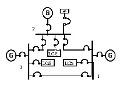
Navy Ships use three phase power generated and distributed in an ungrounded delta configuration. Ungrounded systems are used to ensure continued operation of the electrical system despite the presence of a single phase ground. The voltages are generated at levels of 450 volts a.c. at 60 hertz. The most popular topology used in Navy electrical system is a ring configuration of the generators which provides more flexibility in terms of generation connection and system configuration. In this type of topology, any generator can provide power to any load. This feature is of great importance in order to ensure supply of power to vital loads if failure of an operating generating unit occurs.
Generator switchboards are composed of one or more switchgear units and are located close to their associated generators. Further the generator switchboards are composed of three sections: one section contains the generator breaker, generator controls, breaker controls, and protective devices; the other two sections contain a bus tie breaker, load center breakers, and breakers for major loads.
Figure 1 illustrates a three generator system in the ring configuration; in typical operation two of the generators would be used for normal operation with the remaining generator serving as emergency supply. Bus tie circuits interconnect the generator switchboards which allows for the transfer of power from one switchboard to another.
In general, the Navy distribution system consists of switchboards, transformers, power panels, bus transfer units and interconnecting cable used for delivering power to the loads. A shipboard electrical distribution system contains loads that require power at 440, 115, and 4,160 volts at 60 hertz, and 440 and 115 volts at 400 hertz. The loads requiring 400 hertz are typically part of the command and surveillance systems, weapons systems, and aircraft and aviation support equipment. The 4,160 volt loads are typically associated with aircraft carriers. The interfaces used between the 60 hertz and 400 hertz systems are either motor-generator sets or static solid-state frequency converters.
Load center distribution, which is a modification of radial distribution, is used below the generator switchboard level. This configuration is illustrated in Figure 2 for
one generator switchboard. One or more load center switchboards are connected to each generator switchboard to supply power to load concentrations in various areas of the ship. The load center switchboards supply power to power panels or individual loads, either directly or via automatic bus transfer (ABTs) or manual bus transfers (MBTs). Power distribution panels are centrally located to the loads that they feed.
They provide control and protection of selected portions of the power or lighting distribution systems and special power distribution systems.
| Are you interested in this topic.Then mail to us immediately to get the full report.
email :- contactv2@gmail.com |
